


Plastic optical fiber is very simple and quick to install and requires hardly any tools. However, during the installation process, issues may arise that hinder the success of an installation that provides 100% connectivity, which is the main purpose of this technology. The good news is that in the vast majority of cases, the errors made are very minor and can be easily resolved with a little attention to detail.
A good understanding of how Plastic Fiber technology works is key to helping reduce these errors. While POF is very simple and robust, there are details to consider. Below, we detail the most frequent errors and their solutions.
The essential preliminary step: Checking all materials

It may sound very obvious, but if we are going to install fiber through conduits in the walls, it can be very annoying to discover that some purchased item does not work correctly after we have already completed the entire process. This happens very rarely, but to avoid such a situation, it is best to always check all materials before installing them. In addition, this simple check will give us a better visualization of the installation we plan to carry out. This step is especially important if it is the first time you are installing POF.
We will take all the components out of their boxes, power them with their power supplies, and connect them with all active elements. This should be done as if it were a drill. In this way, we will already see if everything connects well and we will be able to detect a possible malfunction of any of the components.
Key differences between Snap Data POF converters

All converters incorporate an indicator (green LED) under the fiber connector that facilitates the detection of "failures" in the optical signal. It is important to note that this lights up steadily, with the exception of the ACT1001, if optical communication is established between the two ends of the fiber without the need for connection to other equipment such as the router, PC, TV, etc., via the RJ45s. Once data flow occurs between the two pieces of equipment, this indicator will start flashing. This is very helpful in checking fiber connectivity, as these converters do not work if the light signal arrives very attenuated. The advantage is that their reliability, once properly installed, is the highest if done correctly, as this system will either work 100% or not at all. This way, we will always know if we have installed everything correctly or if we need to review something.
In the case of the more compact ACT1001, it is different, as it is designed to work even with a damaged optical signal. The ACT1001 incorporates ABR functionality, which allows data exchange with a more attenuated optical signal by reducing the transmission speed. Furthermore, on this device, the green optical link establishment indicator will not be steady but flashing, and only when data transmission occurs. While there is no information exchange, this LED will not be visible. This has both good and bad aspects: although the converter is capable of establishing an optical signal in less-than-ideal conditions, in some cases, it will do so at the cost of losing part of our bandwidth, and we will not have these lights to warn us where the problem might be. The absence of lit LEDs only indicates that there is no transmission, but it does not inform us of where the problem lies, although, almost certainly, it will be in the installation. We will have to check it ourselves with other methods or by discarding possible sources of error. This must be taken into account if we see that the signal received by an ACT1001 converter is not 100% of what was contracted. If we do not get 100% (always within the 1 Gbps limit), it means there is some kind of fault in the installation.
Four basic checks in case of error
Now we move on to the list of basic checks to make a seamless connection that gives us 100% of what was contracted.
1. Check the fiber cut: The cut we make to the plastic fiber is very important because it ensures that the light enters in a higher percentage without reflections in the fiber's core. If the fiber core does not have a clean cut, it is as if glasses were dirty or foggy, and the light will not enter our optical fiber in the best conditions, losing part of the optical power even before traveling through it. For this, we provide a specific cutter in our kits that provides a dry, perpendicular, and clean cut. In addition, we must try not to overuse the same cutting hole, since every time we make one, even if we don't see it, the blade deteriorates at those points, causing worse, less clean cuts. That is why the cutter incorporates several cutting holes, to allow for changing positions.
-min.jpg)
2. Check the correct separation of the cable fibers: The POF cable is dual, meaning it's like two small tubes joined together, through which light travels in two directions, back and forth. To make the connection, before cutting the cable, we must properly separate the tubes that make up the cable into two parts. They must be well separated, at least 4 or 5 fingers wide, to ensure that the fiber enters completely aligned with the connector hole. If not done this way, when inserted, the fiber might enter somewhat forced, causing the light beam not to penetrate entirely, or to do so obliquely, into the fiber core, losing part of its power and, therefore, reducing the signal quality.

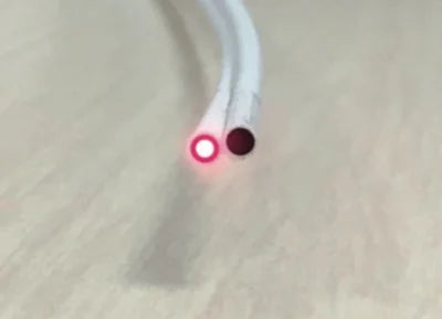
3. Check that the fiber fully enters the POF port, approx. 2cm: When inserting the fiber into the converter, you must ensure that it "bottoms out", meaning it enters at least 2 cm into the converter. Sometimes a mechanical interference can occur between the fiber and the connector hole, giving us the impression that the cable has gone all the way in when it hasn't. To avoid this error, we will ensure that the cable enters at least 2 cm into the POF port.

4. Minimize excessive bends in the installation: Being very flexible and resistant, POF can give us the impression of being indestructible, and while this is true, in installations with medium-long cable runs (more than 35 meters), pronounced bends can occur that reduce signal power, introducing more attenuation than desired, especially in junction boxes or connection boxes. At these points, we should always try to minimize bends whenever possible.
Summary

It is important to understand the concepts of light power and attenuation in a fiber optic installation, whether plastic or glass. Fiber optics works with light, and if the light does not arrive properly, neither will our signal. There are several factors that can attenuate the light signal and that we must try to avoid; sometimes it is not just one detail, but rather small details that, when combined, end up causing the problem.
In summary, we can say that normally by cutting well, separating the fibers sufficiently, and ensuring that the fiber reaches the bottom of the connector, more than 80% of errors will be resolved.
If you have checked everything and are still unable to find the solution, as always, we invite you to contact us at info@actelser.com so that we can resolve your doubts.


